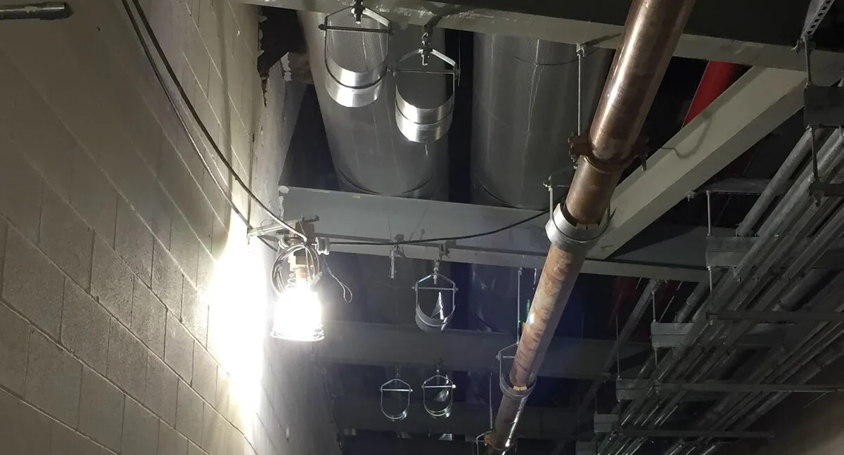
Containment and Mechanical Support Calculations, Including Fire Rating
Calculations for the brackets, drop rods, channel and fixings that hold cable tray, basket and ladder, pipework and ductwork — checked at normal conditions and for the fire duration set by the project's fire strategy. For the cables themselves we calculate pulling tensions and the short-circuit forces on cleats.
Every wiring system must be supported so that it will not collapse early in a fire. BS 7671
Regulation 521.10.202 applies to the whole installation, not only escape routes. Where circuits
must keep working in a fire, such as life-safety and fire-fighting systems, the supports must hold
for the duration the project's fire strategy sets for those circuits. BS 8519 is the code of
practice for these fire-resistant cable systems.
Contractors and designers usually need calculations when electrical and mechanical services share
one support, when tiers are stacked, when supports hang from a deck or steelwork, or when the
specification asks for evidence that the supports comply.
We Check the Whole Support Network
Real supports are networks, not single trapezes: headers carry channel legs, rods hang from
bearers, and cable tray, pipework and ductwork share one fixing. We follow the load from every
service through each element down to the fixing in the structure, so a shared header or a leg
carrying two bearers is checked for everything it really holds.
One rod hangs from the channel of the bracket above, the other from the slab. Every service is followed through the channels to each fixing, and the reaction at each fixing is given for the structural engineer. Open full size
Pipework and Ductwork
We check hangers, brackets and multi-service racks for mechanical services as well: pipework
with the water it carries, its insulation, valves and fittings, and ductwork with its insulation.
Forces at pipe anchors and guides from thermal movement are taken from the mechanical designer.
Where pipework or ductwork shares a support with fire-rated cables, the whole support is checked
for the fire duration — the pipes and ducts still hang from it in a fire.
We provide a full report with the calculations: the loads on each support, every check at normal
conditions and in fire, and the reactions at the fixings.
At normal temperature we check strength and deflection against the manufacturer's published
capacities. In the fire case every service still hangs from the supports while the steel loses
most of its strength, so we check against the manufacturer's fire-test capacities for the required
duration. A support carries the rating of the most demanding circuit on it: one fire-rated basket
low down sets the rating for everything above it.
Fire usually governs. A rod or channel working at a small part of its capacity at normal
temperature can be close to its limit at 120 minutes. Where an element fails, we say what replaces
it — for example a channel leg instead of a drop rod.
Illustrative only: steel loses most of its strength in fire while the load stays the same. Open full size
Cable Pulling and Short-Circuit Forces
Supports are only part of a cable route. For large cables we also calculate the forces on the
cables themselves: while they are pulled in, and when a short circuit drives them apart.
Cable Pulling
We calculate the pulling tension along the route and the side-wall pressure at each bend, allowing for friction on the rollers and the containment. Then three checks against the cable manufacturer's limits: the tension stays below the maximum pulling tension, the side-wall pressure stays below its maximum, and no bend is tighter than the minimum bending radius. The result shows which end to pull from and the tension the winch must not exceed.
Cleats and Short-Circuit Forces
We calculate the force between single-core cables during a short circuit from the peak fault current, and check it against each cleat's tested short-circuit withstand. The result is the maximum cleat spacing for trefoil or flat formation, and the cleat to use.
Ladder and Tray Loading
We check the weight of the cables against the safe working load of the ladder or tray at the support spacing, so the containment is checked as well as its supports.
Loads from every service: cables, tray, pipework full of water, insulation and ductwork
Drop rod tension at normal temperature and in fire, against the manufacturer's tested capacities
Bending strength of channel, brackets and headers
Deflection at normal conditions
Channel nuts, fittings and connections
Fixings and anchors into concrete, deck or steelwork
A load balance: the reactions at the fixings add up to the load applied
Cable pulling tension and side-wall pressure, against the cable manufacturer's limits
Short-circuit forces on cleats, and the maximum cleat spacing
Ladder and tray loading at the support spacing
Evidence a Checker Can Follow
Every capacity in the calculation is traced to its source: fire-test data from the approved product
submittals rather than catalogue figures, and anchor capacities from the product's European
Technical Assessment (ETA), including its fire resistance. Every calculation shows its inputs,
formulas and results, so a checker can follow every number.
Assumptions and exclusions are stated on the front sheet. The capacity of the slab, deck or
steelwork above is for the structural engineer — we give the reactions at every fixing. Anchor
proof testing on site to BS 8539 is carried out by the installer — we give the design loads.
What You Receive
A full report with the calculations (PDF) for each support type or zone
An evidence register naming the source of every capacity used
Marked-up support details, showing any element that must change
The reactions at each fixing, for the structural engineer
A list of the values to confirm on site
Cable pulling and cleat spacing calculations, where the job needs them
What We Need From You
Containment layouts and sections, or views from the BIM model
The cables on each route: types, sizes and numbers
Pipework and ductwork on the supports: sizes, materials, contents and insulation
Any anchor or guide forces from the mechanical designer
Support details: rod sizes, channel types, fixings and spacing
The fire rating each circuit needs
Product submittals, or the manufacturer you plan to use
For pulling and cleat checks: the cable routes with their bends, and the fault level or the protection study
Common questions about containment and mechanical supports.
Do you check pipework and ductwork supports?
Yes. We check hangers, brackets and shared racks for pipework and ductwork, including the water in the pipes and the insulation. Where they share a support with fire-rated cables, the whole support is checked for the fire duration.
Which fire duration do you check?
The duration the project's fire strategy sets for the most demanding circuit on the support — often 30, 60 or 120 minutes. Everything else on that support is checked for the same duration.
Do cable supports need to be fire rated?
BS 7671 Regulation 521.10.202 requires every wiring system to be supported so that it will not collapse early in a fire. Where circuits must keep working in a fire, the supports must hold for the duration the project's fire strategy sets, which we check against the manufacturer's tested fire performance.
Why does the fire case usually govern?
Steel loses most of its strength at fire temperatures while the load stays the same: every cable and tray still hangs. A rod working at a small part of its capacity at normal temperature can be close to its limit after 120 minutes.
Can you work with any manufacturer's products?
Yes, where the manufacturer publishes tested data for the products, including fire-test data for the duration needed. The evidence register names the source of every capacity.
Do you check the structure the supports hang from?
No. We give the reactions at every fixing so the structural engineer can confirm the slab, deck or steelwork. Anchor proof tests on site to BS 8539 are carried out by the installer, using the design loads we give.
Can you check supports that are already installed?
Yes. Send photos, dimensions and the cable routes, and we check the existing supports and say which elements need to change.
Do you calculate cable pulling tensions and cleat spacing?
Yes. For large cables we calculate the pulling tension and the side-wall pressure at each bend, and the short-circuit force between cleated cables, which sets the maximum cleat spacing. Both are checked against the manufacturers' data for the cable and the cleat.
Do you produce the support drawings?
We mark up the support details with any changes. Full support layouts and sections in AutoCAD are available through our drawings and schematics service.
Need Support Calculations?
Send the containment layouts and cable routes — we'll confirm the scope, the inputs we need, and the cost.