MEP Bracket Calculator
Calculation basis and reference data
Every number this calculator uses, where it came from, and how each check is worked out. Written to be reproduced: if you cannot follow a figure on an issued sheet back to a catalogue page or a clause here, that is a fault in this document.
How a bracket is calculated
Weight starts on the containment and ends in the structure. Every check asks the same question at a different point on that path: can this part carry what is passing through it?
Lh it becomes a weight sitting on one bracket, at the position it
actually occupies. That weight bends the channel, divides between the rods according to where it
sits, and arrives at the structure through the fixings. Each check below sits at one point on
this path.There are six checks on a plain bracket, plus two more that appear only when they apply. They are all the same shape: a demand computed from the load, against a capacity read from a catalogue or a standard, reported as a percentage. Nothing passes on a missing capacity — a value the tool does not hold reads NO DATA, never a silent pass.
Channel capacity
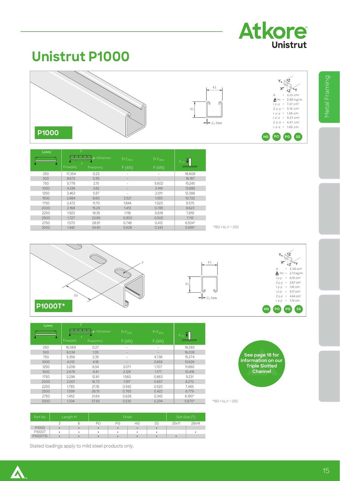
The bearer's strength and stiffness, straight off the manufacturer's load table. One row per span, three ambient columns and — on the fire-rated sections — three more.
The Fmax column is a strength value: the total uniformly distributed
load the section carries on a simply supported span at an allowable bending stress of
σ = 175 N/mm². The L/200 and L/360 columns are
deflection values — the load at which the span sags to that fraction of its length.
Where the catalogue prints a dash, deflection does not govern at that span, or the section is off
the end of its published deflection table.
| ambient | |||
|---|---|---|---|
| Span m | Fmax kN | L/200 kN | L/360 kN |
| 0.25 | 16.069 | — | — |
| 0.50 | 8.034 | — | — |
| 0.75 | 5.356 | — | 4.738 |
| 1.00 | 4.012 | — | 2.659 |
| 1.25 | 3.208 | 3.071 | 1.707 |
| 1.50 | 2.678 | 2.129 | 1.177 |
| 1.75 | 2.296 | 1.56 | 0.863 |
| 2.00 | 2.001 | 1.197 | 0.657 |
| 2.25 | 1.785 | 0.942 | 0.52 |
| 2.50 | 1.599 | 0.765 | 0.422 |
| 2.75 | 1.452 | 0.628 | 0.343 |
| 3.00 | 1.334 | 0.53 | 0.294 |
| fire-tested | |||
|---|---|---|---|
| Span m | 30 min kN | 1 h kN | 2 h kN |
| 0.50 | 6.0255 | 3.37428 | 1.607 |
| 0.75 | 4.017 | 2.24952 | 1.071 |
| 1.00 | 3.009 | 1.68504 | 0.802 |
| 1.25 | 2.406 | 1.34736 | 0.642 |
| 1.50 | 2.0085 | 1.12476 | 0.536 |
| 1.75 | 1.722 | 0.96432 | 0.459 |
| over 1.75 | not published — the edge of the test, see section 8 | ||
| ambient | |||
|---|---|---|---|
| Span m | Fmax kN | L/200 kN | L/360 kN |
| 0.75 | 16.363 | — | — |
| 1.00 | 12.272 | — | — |
| 1.25 | 9.82 | — | — |
| 1.50 | 8.182 | — | 7.034 |
| 1.75 | 7.014 | — | 5.17 |
| 2.00 | 6.131 | — | 3.953 |
| 2.25 | 5.454 | — | 3.12 |
| 2.50 | 4.905 | 4.552 | 2.531 |
| 2.75 | 4.464 | 3.767 | 2.09 |
| 3.00 | 4.091 | 3.159 | 1.756 |
| fire-tested | |||
|---|---|---|---|
| Span m | 30 min kN | 1 h kN | 2 h kN |
| 0.75 | 12.2723 | 6.8276 | 3.2726 |
| 1.00 | 9.204 | 5.15242 | 2.4544 |
| 1.25 | 7.365 | 4.1244 | 1.964 |
| 1.50 | 6.1365 | 3.43644 | 1.6364 |
| 1.75 | 5.2605 | 2.94588 | 1.4028 |
| 2.00 | 4.59825 | 2.57502 | 1.2262 |
| over 2.00 | not published — the edge of the test, see section 8 | ||
One error worth knowing. The Material Approval Request prints the
ambient load at 1.50 m as 2.0678 kN. The catalogue gives 2.678. The
sequence 3.208 → 2.0678 → 2.296 is not monotonic, which a load/span curve cannot be,
and the fire values at that span are 0.75 / 0.42 / 0.20 of 2.678. It is a digit
transposition in the submittal; this tool holds the catalogue value.
A plain structural channel
Two hot-rolled channels are offered beside the Unistrut sections, each usable either way up. Their tables are the only ones in this document that nobody published — they are calculated, so the calculation is set out here in full.
Unistrut print load/span tables because the channel is their product. A 76 × 38
tapered flange channel or a 100 × 50 parallel flange channel is a
structural section: no manufacturer publishes a bracket load table for one, and none will. You
calculate it. That is not a weaker footing than a transcription — it is the same identity
section 7 shows holding to 0.02 % down Unistrut's own printed column, run on a different
Z.
| web vertical | laid flat | ||||||
|---|---|---|---|---|---|---|---|
| Section | kg/m | A cm2 | Ixx cm4 | Zxx cm3 | Iyy cm4 | Zyy cm3 | Source |
| 76×38×6.71 TFC (BS 4-1) | 6.710 | 8.56 | 74.3 | 19.5 | 10.7 | 4.09 | BS 4-1 not in P363 |
| 100×50×10 PFC (SCI P363) | 10.200 | 13.00 | 208 | 41.5 | 32.3 | 9.9 | SCI P363 Blue Book |
The three formulae
σ = 165 N/mm² is 0.6 × the 275 N/mm² yield of S275. With the
tool's default load factor of 1.3 that is 2.17 overall against yield, which sits alongside the 2.08
implied by Unistrut's own σ = 175. It is a choice, not a published value, and it
is the one figure on this page most worth agreeing before you rely on a result.
Fire needs no test. BS 8519:2020 Annex E is normative, and it says the stresses in Table E.1 apply to unprotected drop rods and bearers made of mild steel. A plain steel bearer is a bearer. So the fire columns are the same formula at 9 / 9 / 6 N/mm² — the standard applied directly, rather than read across from a furnace test of a different arrangement the way section 8 has to do for the FR strut.
| Catalogue section | Limit | Values | I back-solved cm4 | Range | Spread |
|---|---|---|---|---|---|
| P1000T | L/200 | 8 | 5.925 | 5.889 - 5.950 | 1.04% |
| P1000T | L/360 | 10 | 5.897 | 5.790 - 5.954 | 2.82% |
| P1001TFR | L/200 | 3 | 35.288 | 35.257 - 35.327 | 0.20% |
| P1001TFR | L/360 | 7 | 35.298 | 35.257 - 35.342 | 0.24% |
| P3300T10 | L/200 | 5 | 1.015 | 1.014 - 1.016 | 0.16% |
| P3300T10 | L/360 | 4 | 1.015 | 1.015 - 1.016 | 0.08% |
W = 384EI/(5rL²) is the relationship behind a published
deflection column, then I comes back the same off every span in it. It does —
to a fifth of a percent on the two sections printed to four significant figures. The P1000T's
columns are printed to 3 dp and one row (2.75 m, L/360) sits about 2 % off the rest, which is
what widens its spread. Note the back-solved I is a few percent under the gross
I published for that section: it is continuously slotted. A plain channel has no
slots, so its gross I is used as published.Which way up
x-x; laid flat they move in to
the y-y axis and Z falls with them. Flat is drawn web-up, so the
containment lands on a flat face and the flanges hang as legs.| ambient, 165 N/mm2 | fire, BS 8519 Table E.1 | |||||
|---|---|---|---|---|---|---|
| Span m | Fmax kN | L/200 kN | L/360 kN | 30 min kN | 1 h kN | 2 h kN |
| 0.25 | 102.960 | 958.648 | 532.582 | 5.616 | 5.616 | 3.744 |
| 0.50 | 51.480 | 239.662 | 133.146 | 2.808 | 2.808 | 1.872 |
| 0.75 | 34.320 | 106.516 | 59.176 | 1.872 | 1.872 | 1.248 |
| 1.00 | 25.740 | 59.916 | 33.286 | 1.404 | 1.404 | 0.936 |
| 1.25 | 20.592 | 38.346 | 21.303 | 1.123 | 1.123 | 0.749 |
| 1.50 | 17.160 | 26.629 | 14.794 | 0.936 | 0.936 | 0.624 |
| 1.75 | 14.709 | 19.564 | 10.869 | 0.802 | 0.802 | 0.535 |
| 2.00 | 12.870 | 14.979 | 8.322 | 0.702 | 0.702 | 0.468 |
| 2.25 | 11.440 | 11.835 | 6.575 | 0.624 | 0.624 | 0.416 |
| 2.50 | 10.296 | 9.586 | 5.326 | 0.562 | 0.562 | 0.374 |
| 2.75 | 9.360 | 7.923 | 4.402 | 0.511 | 0.511 | 0.340 |
| 3.00 | 8.580 | 6.657 | 3.698 | 0.468 | 0.468 | 0.312 |
8σZ/L at σ = 165 N/mm² ambient and BS 8519 Table E.1 in fire; 384EI/(5rL²) for deflection. Properties BS 4-1 not in the Blue Book. Assumes the compression flange is restrained — see below.| ambient, 165 N/mm2 | fire, BS 8519 Table E.1 | |||||
|---|---|---|---|---|---|---|
| Span m | Fmax kN | L/200 kN | L/360 kN | 30 min kN | 1 h kN | 2 h kN |
| 0.25 | 21.595 | 138.056 | 76.698 | 1.178 | 1.178 | 0.785 |
| 0.50 | 10.798 | 34.514 | 19.174 | 0.589 | 0.589 | 0.393 |
| 0.75 | 7.198 | 15.340 | 8.522 | 0.393 | 0.393 | 0.262 |
| 1.00 | 5.399 | 8.628 | 4.794 | 0.294 | 0.294 | 0.196 |
| 1.25 | 4.319 | 5.522 | 3.068 | 0.236 | 0.236 | 0.157 |
| 1.50 | 3.599 | 3.835 | 2.130 | 0.196 | 0.196 | 0.131 |
| 1.75 | 3.085 | 2.817 | 1.565 | 0.168 | 0.168 | 0.112 |
| 2.00 | 2.699 | 2.157 | 1.198 | 0.147 | 0.147 | 0.098 |
| 2.25 | 2.399 | 1.704 | 0.947 | 0.131 | 0.131 | 0.087 |
| 2.50 | 2.160 | 1.381 | 0.767 | 0.118 | 0.118 | 0.079 |
| 2.75 | 1.963 | 1.141 | 0.634 | 0.107 | 0.107 | 0.071 |
| 3.00 | 1.800 | 0.959 | 0.533 | 0.098 | 0.098 | 0.065 |
Zy. Properties BS 4-1 not in the Blue Book. No lateral-torsional buckling to check this way up.| ambient, 165 N/mm2 | fire, BS 8519 Table E.1 | |||||
|---|---|---|---|---|---|---|
| Span m | Fmax kN | L/200 kN | L/360 kN | 30 min kN | 1 h kN | 2 h kN |
| 0.25 | 219.120 | 2683.699 | 1490.944 | 11.952 | 11.952 | 7.968 |
| 0.50 | 109.560 | 670.925 | 372.736 | 5.976 | 5.976 | 3.984 |
| 0.75 | 73.040 | 298.189 | 165.660 | 3.984 | 3.984 | 2.656 |
| 1.00 | 54.780 | 167.731 | 93.184 | 2.988 | 2.988 | 1.992 |
| 1.25 | 43.824 | 107.348 | 59.638 | 2.390 | 2.390 | 1.594 |
| 1.50 | 36.520 | 74.547 | 41.415 | 1.992 | 1.992 | 1.328 |
| 1.75 | 31.303 | 54.769 | 30.427 | 1.707 | 1.707 | 1.138 |
| 2.00 | 27.390 | 41.933 | 23.296 | 1.494 | 1.494 | 0.996 |
| 2.25 | 24.347 | 33.132 | 18.407 | 1.328 | 1.328 | 0.885 |
| 2.50 | 21.912 | 26.837 | 14.909 | 1.195 | 1.195 | 0.797 |
| 2.75 | 19.920 | 22.179 | 12.322 | 1.087 | 1.087 | 0.724 |
| 3.00 | 18.260 | 18.637 | 10.354 | 0.996 | 0.996 | 0.664 |
| ambient, 165 N/mm2 | fire, BS 8519 Table E.1 | |||||
|---|---|---|---|---|---|---|
| Span m | Fmax kN | L/200 kN | L/360 kN | 30 min kN | 1 h kN | 2 h kN |
| 0.25 | 52.272 | 416.748 | 231.526 | 2.851 | 2.851 | 1.901 |
| 0.50 | 26.136 | 104.187 | 57.882 | 1.426 | 1.426 | 0.950 |
| 0.75 | 17.424 | 46.305 | 25.725 | 0.950 | 0.950 | 0.634 |
| 1.00 | 13.068 | 26.047 | 14.470 | 0.713 | 0.713 | 0.475 |
| 1.25 | 10.454 | 16.670 | 9.261 | 0.570 | 0.570 | 0.380 |
| 1.50 | 8.712 | 11.576 | 6.431 | 0.475 | 0.475 | 0.317 |
| 1.75 | 7.467 | 8.505 | 4.725 | 0.407 | 0.407 | 0.272 |
| 2.00 | 6.534 | 6.512 | 3.618 | 0.356 | 0.356 | 0.238 |
| 2.25 | 5.808 | 5.145 | 2.858 | 0.317 | 0.317 | 0.211 |
| 2.50 | 5.227 | 4.167 | 2.315 | 0.285 | 0.285 | 0.190 |
| 2.75 | 4.752 | 3.444 | 1.913 | 0.259 | 0.259 | 0.173 |
| 3.00 | 4.356 | 2.894 | 1.608 | 0.238 | 0.238 | 0.158 |
Zy. Properties SCI P363 Blue Book. No lateral-torsional buckling to check this way up.Fire: two bases, and the standard's is the default
A plain section can be checked either way. BS 8519 Table E.1 is the default: one blanket allowable stress for any unprotected mild-steel rod or bearer, normative, needing no test. It is also a single set of numbers for every section and every rating, and Annex E says it is drawn from what manufacturers of fire-rated ductwork publish — so a designer entitled to calculate instead may, and the route is fully standardised.
| Step | What is used | Published source |
|---|---|---|
| The fire | Standard temperature-time curve, 20 + 345 log10(8t + 1) | BS EN 1363-1 / ISO 834 / EN 1991-1-2 3.2.1 |
| Heat into the steel | Unprotected internal steelwork, stepped in time | EN 1993-1-2 4.2.5.1 formula (4.25) |
| Convection | alpha-c = 25 W/m2K | EN 1991-1-2, standard curve |
| Radiation | emissivity 0.7 (member) x 1.0 (fire), Phi = 1.0 | EN 1993-1-2 2.2(2); EN 1991-1-2 3.1(6) |
| Specific heat | temperature-dependent, incl. the 735 C phase change | EN 1993-1-2 3.4.1.2 (3.2a)-(3.2d) |
| Strength left | k(y,theta), effective yield retention | EN 1993-1-2 Table 3.1 |
| Material factor | gamma-M,fi = 1.0 (fire is the accidental case) | EN 1993-1-2 2.3(1) |
| EN 1993-1-2 4.2.5.1 + Table 3.1 | against the blanket table | |||||||
|---|---|---|---|---|---|---|---|---|
| Section | Am/V /m | Rating | Gas C | Steel C | k(y,theta) | calculated N/mm2 | Table E.1 | ratio |
| 76×38×6.71 TFC | 343 | 30 min | 842 | 836 | 0.0921 | 25.32 | 9 | 2.81x |
| 76×38×6.71 TFC | 343 | 1 h | 945 | 943 | 0.0513 | 14.12 | 9 | 1.57x |
| 76×38×6.71 TFC | 343 | 2 h | 1049 | 1048 | 0.0303 | 8.35 | 6 | 1.39x |
| 100×50×10 PFC | 300 | 30 min | 842 | 835 | 0.0926 | 25.47 | 9 | 2.83x |
| 100×50×10 PFC | 300 | 1 h | 945 | 943 | 0.0514 | 14.13 | 9 | 1.57x |
| 100×50×10 PFC | 300 | 2 h | 1049 | 1048 | 0.0304 | 8.35 | 6 | 1.39x |
| steel temperature | |||||
|---|---|---|---|---|---|
| Section | Am/V /m | 30 min C | 1 h C | 2 h C | 2 h N/mm2 |
| C 76x38 TFC | 343 | 836 | 943 | 1048 | 8.35 |
| PFC 100x50 | 300 | 835 | 943 | 1048 | 8.35 |
| furnace gas | — | 842 | 945 | 1049 | — |
Do not specify one for fire on its ambient strength
The 76 × 38 on edge is more than six times the fire-rated strut at ambient. At two hours that advantage is all but gone.
| moment capacity, ambient | moment capacity, 2 h | |||
|---|---|---|---|---|
| Section | ambient kN.m | vs FR strut | 2 h kN.m | vs FR strut |
| fire-tested strut | 0.5021 | 1.00x | 0.1005 | 1.00x |
| C 76×38 TFC — web vertical | 3.2175 | 6.41x | 0.1170 | 1.16x |
| C 76×38 TFC — laid flat | 0.6748 | 1.34x | 0.0245 | 0.24x |
| PFC 100×50 — web vertical | 6.8475 | 13.64x | 0.2490 | 2.48x |
| PFC 100×50 — laid flat | 1.6335 | 3.25x | 0.0594 | 0.59x |
The “20 % in fire” figure, and why it does not apply here. It circulates as though it were a rule, and it is a real number: the FR strut's published fire columns are exactly 0.20 of its ambient strength at two hours (and 0.75 / 0.42 at 30 min and 1 h), which on its σ of 175 N/mm² is an allowable of 35. But that is one product's furnace test result, and BS 8519 says exactly how it is earned — clause 12 allows a proprietary alternative its own numbers where it has been tested to the BS EN 1363-1 fire curve and shown to carry the load for the survival time. A hot-rolled channel has not been tested, so the route open to it is the calculation one, and that is Table E.1. Applying 20 % to a plain section would be 5.5× the standard's own figure (165/6 × 0.2 = 33 N/mm² against 6) and would claim a bare unprotected channel out-performs a fire-tested FR strut 6.4 : 1 at two hours, on no test at all. For scale: 33 N/mm² is a yield retention of 0.12 on S275, which EN 1993-1-2 Table 3.1 puts at roughly 790 °C steel — while the furnace is near 1,050 °C at 120 minutes and a thin unprotected section is not far behind it. If Table E.1 makes a plain section unworkable, the standard's answer is a furnace-tested system, not a more generous assumed percentage. (The only 20 % in BS 8519 itself is unrelated: Annex E asks for a 20–30 % spare capacity allowance for future extension.)
And note what the calculated basis above actually returns: 8.35 N/mm² at two hours, about 5 % of ambient — not 20 %. The two routes this tool offers bracket the honest answer between 3.6 % and 5.1 %. If you want more than that from a plain section in a two-hour fire, the section is not the answer: an unprotected member is at roughly 1,050 °C in that furnace, and steel keeps almost nothing at 1,050 °C.
Three things a published strut table already answers
None of these can be calculated here — the tool does not know where you will drill, how the containment is fixed down, or where the load lands across the flange. So it says each of them on the sheet instead, and warns on the one case it can see.
- Holes. EN 1993-1-1 §6.2.5: a hole in the compression zone needs no allowance where a fastener fills it; one in the tension flange or the web tension zone may only be ignored where the net section still develops the gross yield. On a cantilever the top flange is the tension flange, so a rod hole over the support is not free there. And unlike Unistrut, whose published capacity has its slots already in it, a derived capacity is the gross section — drilling it is a deduction they never had to make.
- Lateral-torsional buckling, web vertical only. The top flange is in compression, and a
compression flange free to move sideways buckles out of plane well before the section reaches
σZ. The tables above assume it is restrained — containment bolted down at roughly 400 mm centres or closer, which is the normal arrangement. Where a bearer plainly has no such restraint (nothing on it, or its load hanging below on rods) the tool raises a warning; the cases in between are the engineer's. Laid flat there is no lateral-torsional buckling at all — bending is already about the weak axis, so there is no weaker axis to buckle into. That is the trade for a fifth of the capacity. - Torsion. A channel's shear centre lies outside its web, so a vertical load applied in the plane of the web also twists it. Unistrut strut is symmetric about its loading plane and has no such term — and every beam check in this tool is a symmetric-beam model. Load through the shear centre, restrain the section against rotation, or check the torsion by hand. It matters most web-vertical with the load out on one flange, and least laid flat bearing on the web.
Threaded rod
A drop rod is checked on the steel that is actually there — the root of the thread, not the bar it was cut from.
| Rod | Minor dia d3 mm | Area mm2 | Weight kg/m | Source |
|---|---|---|---|---|
| M8 | 6.200 | 30.2 | 0.395 | BS 8519 Table E.2 |
| M10 | 7.858 | 48.5 | 0.617 | BS 8519 Table E.2 |
| M12 | 9.516 | 71.1 | 0.888 | BS 8519 Table E.2 |
| M16 | 13.181 | 136.5 | 1.578 | BS 8519 Table E.2 |
| M20 | 16.529 | 214.6 | 2.466 | BS 8519 Table E.2 |
| M24 | — | 324.26 | 3.550 | basic root area VERIFY |
d3 = d − 1.2269P. The two conventions differ by a roughly fixed 0.3 mm on the
diameter rather than a constant ratio, so M24 cannot be extrapolated from the rest.| Condition | Max stress N/mm2 | Where it comes from |
|---|---|---|
| Ambient | 100 | working stress for mild steel assumed — not from a standard |
| 30 min | 9 | BS 8519:2020 Table E.1 |
| 1 h | 9 | BS 8519:2020 Table E.1 |
| 2 h | 6 | BS 8519:2020 Table E.1 |
Fixings into the structure
The last link, and the one most often assumed. Capacities are per fixing at the characteristic (unfactored) load — a published anchor rating already contains its factor of safety, so applying a load factor on top would count it twice.
| tension per fixing | |||||||
|---|---|---|---|---|---|---|---|
| Fixing | Suits | ambient kN | 30 min | 1 h | 2 h | shear kN | Source |
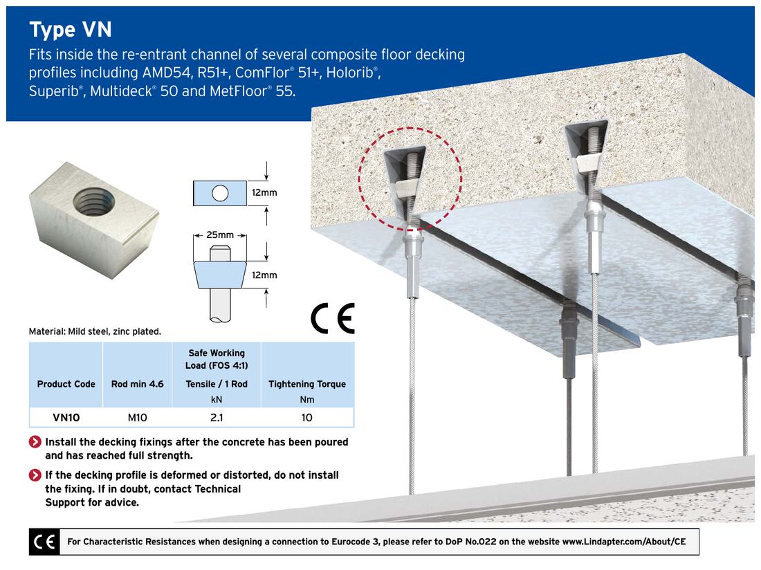
| VN wedge nut (rib deck) | rib deck | 2.1 | 1 | 1 | 0.4 | NO DATA | Lindapter Type VN datasheet p.68 VERIFY |
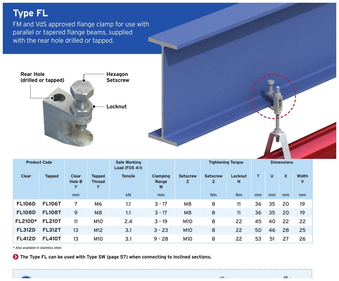
| FL312 flange clamp | steel beam | 3.1 | — | — | — | NO DATA | Lindapter Type FL datasheet p.56 VERIFY |
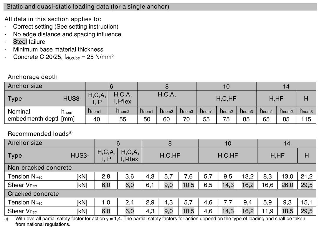
| Hilti HUS3 40mm | concrete | 1 | 0.5 | 0.4 | 0.4 | 6 | Hilti HUS3 technical datasheet (ETA-13/1038, updated Mar-21) p.2, size 6, hnom1 = 40 mm, HUS3-H/C/A/I/P. Ambient 1.00 kN = recommended tension NRec in CRACKED concrete |
| P1796 window clamp | steel beam | 1.45 | — | — | — | NO DATA | Unistrut P1796 window beam clamp VERIFY |
| P1796-B window clamp | steel beam | 1.45 | — | — | — | NO DATA | P1796-B (bigger) window clamp VERIFY |
| Drilled hole + nuts | steel beam | the rod itself, at the stress for the condition | NO DATA | Drilled hole through the flange, full nut + washer each side VERIFY | |||
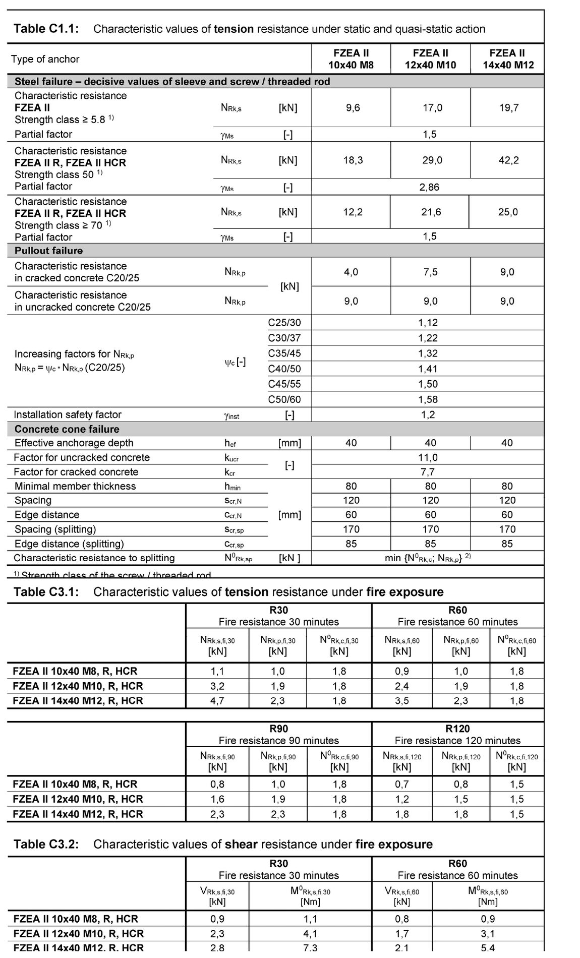
| fischer FZEA II 10x40 M8 | concrete | 1.6 | 1 | 0.9 | 0.7 | 4.74 | fischer Zykon-Hammerset anchor FZEA II 10x40 M8, zinc plated, strength class 5.8 VERIFY |
| fischer FZEA II 12x40 M10 | concrete | 3 | 1.8 | 1.8 | 1.2 | 7.77 | fischer Zykon-Hammerset anchor FZEA II 12x40 M10, zinc plated, strength class 5.8 VERIFY |
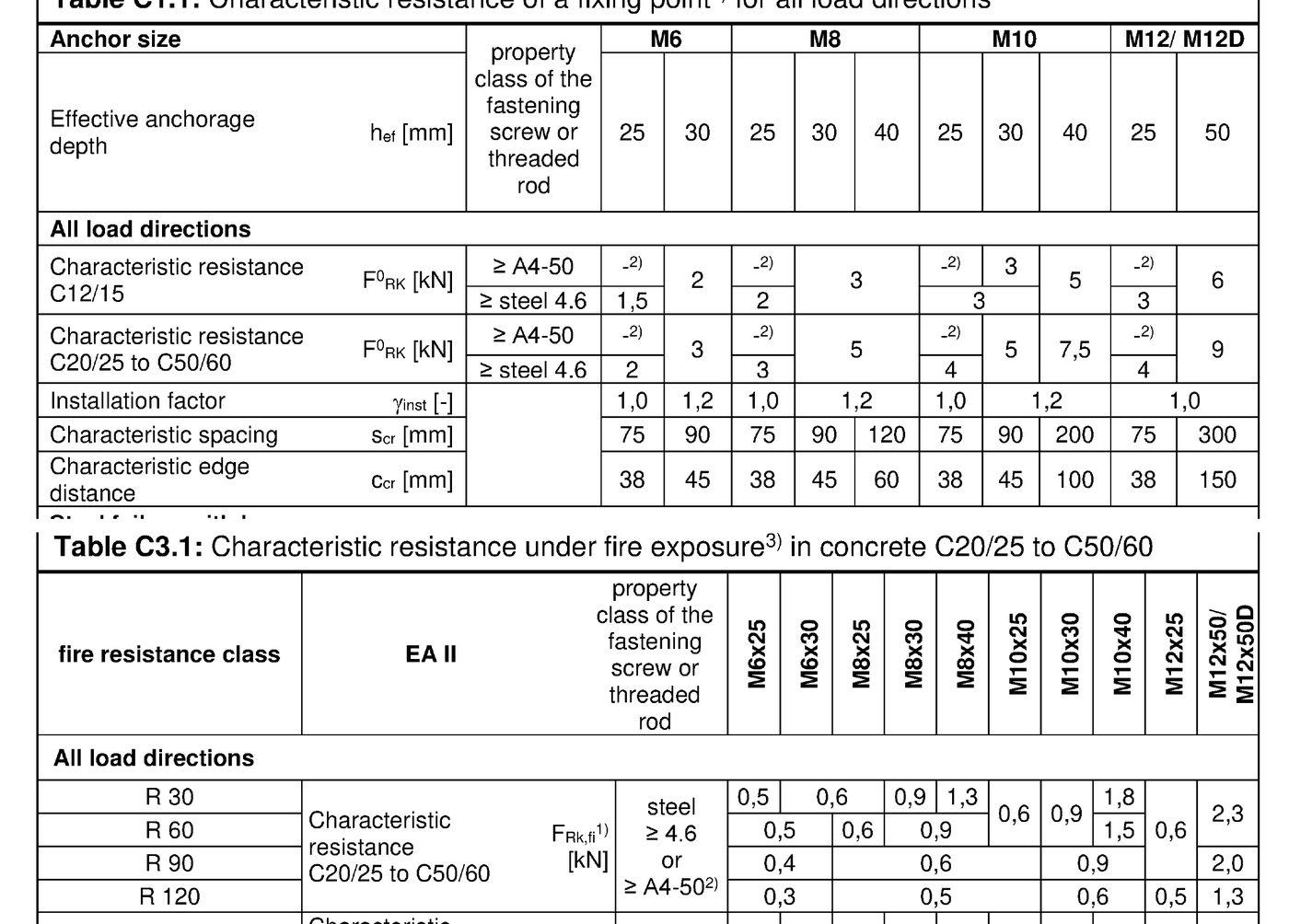
| fischer EA II M10x30 | concrete | 2 | 0.9 | 0.9 | 0.6 | 2 | fischer drop-in anchor EA II M10 x 30, zinc plated VERIFY |
| fischer EA II M10x40 | concrete | 3 | 1.8 | 1.5 | 0.6 | 3 | fischer drop-in anchor EA II M10 x 40, zinc plated VERIFY |
The four load columns are TENSION — a ceiling fixing hangs and is pulled straight out. The shear column is a different mode: a fixing on a WALL carries the same weight across itself. They are not interchangeable, and the difference is not small — the HUS3 is rated 6.00 kN in shear against 1.00 kN in cracked tension, because shear is governed by the anchor’s steel and a cracked cone does not enter it. A blank means that anchor’s document publishes no shear at all, and a wall fixing using it takes NO verdict rather than borrowing the tension figure. Where a shear figure IS held it covers STEEL failure only: concrete pryout and concrete EDGE failure are not included, because no distance to a free edge is held for any fixing — near an edge the concrete governs long before the steel.
Containment and load factors
Containment weight
Each run contributes its published weight per metre — the containment plus its cables — multiplied by the bracket spacing.
| Product | kg/m | Product | kg/m |
|---|---|---|---|
| Trunking 50x50 | 4.700 | Basket 50mm - Comms | 2.785 |
| Trunking 75x50 | 7.100 | Basket 100mm - Comms | 4.987 |
| Trunking 100x50 | 9.000 | Basket 150mm - Comms | 7.391 |
| Trunking 150x50 | 12.750 | Basket 200mm - Comms | 9.770 |
| Trunking 100x75 | 12.200 | Basket 300mm - Comms | 14.739 |
| Trunking 100x100 | 15.700 | Basket 400mm - Comms | 24.830 |
| Trunking 150x150 | 34.100 | Basket 600mm - Comms | 29.323 |
| Tray 100mm | 8.517 | Basket 50mm - ELI | 4.210 |
| Tray 150mm | 13.750 | Basket 100mm - ELI | 7.026 |
| Tray 225mm | 21.767 | Basket 150mm - ELI | 10.506 |
| Tray 300mm | 31.800 | Basket 200mm - ELI | 13.848 |
| Tray 450mm | 43.533 | Basket 300mm - ELI | 20.781 |
| Tray 600mm | 56.983 | Basket 400mm - ELI | 26.728 |
| Basket 50mm - Fire | 1.532 | Basket 600mm - ELI | 41.859 |
| Basket 100mm - Fire | 2.557 | Ladder 300mm | 36.200 |
| Basket 150mm - Fire | 3.708 | Ladder 450mm | 44.433 |
| Basket 200mm - Fire | 4.910 | Ladder 600mm | 60.767 |
| Basket 300mm - Fire | 7.373 | Ladder 750mm | 77.533 |
| Basket 400mm - Fire | 10.170 | Ladder 900mm | 101.567 |
| Basket 600mm - Fire | 14.667 |
Load factors
| Symbol | Meaning | Default | Basis |
|---|---|---|---|
| load factor | ambient | 1.300 | designer's choice, editable |
| load factor | in fire | 1.000 | fire is the accidental case |
| Lh | bracket spacing along the run | 1.500 m | designer's input |
| L/x | deflection limit | L/200 | typical for services; L/360 selectable |
| g | gravity | 9.81 m/s2 | — |
The checks, one by one
Each check is a demand and a capacity. What follows is where each side of that comes from, and the arithmetic between them.
6.1 · A point load is not a spread load
The catalogue capacity is a uniformly distributed load. Real containment lands on the bracket through one fixing, so it is a point load — and a point load bends the channel harder. Each one is converted to the equivalent UDL that would produce the same bending moment:
W·L/8. Concentrated
at mid-span it is P·L/4 — twice as much. Setting the two equal gives
W_eq = 2P at p = 0.5, which is exactly what 8p(1−p)
returns. Near a support the factor falls away to nothing, because a load sitting over a rod bends
nothing at all.6.2 · Between the rods, and past them
A channel is not one member. Between two rods it sags; where it runs on past the outer rod it hogs about that rod. Those are different actions with different arithmetic, so they are separate checks — and with three rods there are two bays, each checked at its own length.
6.3 · Where the moment capacity comes from
A cantilever needs a moment capacity, and the catalogue publishes loads. But an
Fmax is the total UDL on a simply supported span, so the moment it implies is
Fmax·L/8 — and that product is constant all the way down the column, because it
is the section's own allowable moment:
| Span m | Fmax kN | Fmax x L / 8 kN.m | Against sigma x Z = 0.5022 |
|---|---|---|---|
| 0.25 | 16.069 | 0.50216 | -0.02% |
| 1.00 | 4.012 | 0.50150 | -0.15% |
| 2.00 | 2.001 | 0.50025 | -0.40% |
| 3.00 | 1.334 | 0.50025 | -0.40% |
6.4 · Strength and deflection are different questions
6.5 · How the load divides between the rods
Where the load sits decides what each rod carries. For two rods this is BS 8519's own method — Annex I, Formula I.1 — a moment balance about the first rod:
Annex I stops at two rods, and tells you to even out an uneven load or add a factor for it. Three or four rods are statically indeterminate, so the tool solves them with the three-moment (Clapeyron) equation instead — which returns exactly Annex I's answer when there are two.
Why not just divide by the number of rods. A bare three-rod bracket splits 18.75 / 62.5 / 18.75, not 33/33/33. The middle rod carries more than three times what an even split suggests, because the rods are far stiffer than the channel spanning between them — an M12 at 1 m is about 87 times stiffer axially than the channel is in bending.
6.6 · The rod itself
Straight out of BS 8519 Formula E.1. Where a bracket lifts a rod rather than pulling it — which a one-sided cantilever can do — the rod is reported as a positive magnitude with the word uplift and checked as a strut, never as a negative weight.
6.7 · The channel nut a rod hangs on
A hanging threaded rod screws into one channel nut in the slot above it, so the load pulls that nut down and out through the mouth. Atkore's own connection figure marks two directions and tabulates one:
The check therefore reads the published F3 for the actual nut, channel and finish, at the torque the table is written for — see the table in section 09. Only ZP and SS are published, so a hot-dip galvanised job takes the lower of the two and the sheet says so.
This was wrong until August 2026. The check compared that pull-out load against a flat 3.5 kN figure held as a slip capacity — the F4 direction, which nobody publishes — and applied it to every rod regardless of size. For the M12 the tool orders, the published pull-out figure is 8.00 kN zinc plated, so the check was about 2.3× over-conservative: it failed brackets the manufacturer would pass. A slip figure is still held for a genuine slip case, and stays marked as unpublished.
In fire the nut is assumed to keep 20% of its capacity (owner's assumption on a 2 h basis, the same derate as the P1026 leg). That fraction is not a manufacturer's figure — verify it against a fire assessment for the nut specified.
6.7 · Load conservation
Not an engineering check but a guard on the arithmetic: the sum of every element's own weight must equal the sum of what arrives at the structure. If they disagree, a load has been lost or double-counted somewhere in the roll-up, and the sheet says so rather than reporting a tidy answer.
Fire
BS 8519 exists because there is no point in a two-hour cable hanging from a bracket that fails in twenty minutes. Every element is checked twice: at ambient with the load factor, and again at its rating with the whole load still hanging.
The fire factor
Compare the fire columns in section 2 and 3 with the ambient strength column and the relationship is exact, on every span and both sections:
| Rating | P1000TFR | P1001TFR | Reads as |
|---|---|---|---|
| 30 min | 0.750 | 0.750 | steel at roughly 510 C |
| 1 h | 0.420 | 0.420 | roughly 620 C |
| 2 h | 0.200 | 0.200 | roughly 720 C |
What was tested, and what was not
The Unistrut frame builder
The frame tab builds something different from a trapeze bracket: posts and rails fixed to a floor, a soffit, a walkway or a wall, joined by flat and angle fittings rather than hung on threaded rod. Everything below is what it holds and where each figure came from.
What it is fixed to
The model measures height away from whatever the frame is fixed to and always as a positive number, so one field turns a frame over and no dimension has to be re-entered.
| Key | Fixed to | Datum | Which way z runs | What it is |
|---|---|---|---|---|
| slab | Floor — concrete slab | floor | away from the datum, upward | Base channel laid flat, anchored through, with 90° gusset plates bracing each post. |
| soffit | Hung from the soffit | soffit | away from the datum, downward | Head channel anchored up to the slab; posts hang below it. |
| walkway | Bolted to a walkway | walkway | away from the datum, upward | Bracket bolted to a twisted-bar bearer type walkway instead of a slab. |
| wall | Fixed back to a wall | wall | away from the datum, upward | Posts fixed back to a vertical face; z runs up the wall. |
How members are cut
The same rule as a bracket, and it comes off a real drawing note: “the distance between the drop rod centre and end of slotted Unistrut channel to be minimum of 25mm, and cut to be made between slot centres.” Every member is cut half a slot pitch — 25 mm — past its outermost connection at each end, so every bolt lands on a slot centre by construction and there is no snapping step to get out of step.
The four faces, and what each one takes
A channel is not a square tube. It presents an open mouth, a slotted back and two plain webs, and only two of those four take a fixing at all. A bolt into the mouth takes a channel nut, which slides anywhere along the length; a bolt through the back goes through a punched slot, so it can only sit on the 50 mm centres. A plain web takes nothing without drilling, and drilling is a site operation this tool does not schedule.
| Face | What fixes to it | Where it can sit |
|---|---|---|
| Open mouth | Channel nut in the mouth | anywhere along the length |
| Slotted back | Bolt through a slot | 50 mm slot centres only |
| Plain web | nothing without drilling | — |
So turning a channel a quarter turn changes what can be bolted to it, and that is a real decision on the drawing rather than a drafting preference. Below, a vertical post at each of the four turns, and where each of its faces ends up.
| Turn | +x | −x | +y | −y |
|---|---|---|---|---|
| 0° | mouth | slotted back | plain web | plain web |
| 90° | plain web | plain web | mouth | slotted back |
| 180° | slotted back | mouth | plain web | plain web |
| 270° | plain web | plain web | slotted back | mouth |
Each family reads a different pair of faces
A flat fitting lies in the plane of both members, so both must present a mouth or a slotted back along the axis neither of them runs along. An angle turns the corner: its two legs are perpendicular plates, so the faces they bolt to are perpendicular too — the upright lands on one member’s face pointing along the other member, and the foot lands on the other member’s face pointing along the first.
| Family | The face it needs on one member | …and on the other |
|---|---|---|
| Flat plate — P1036, P1031, P1580, P1358 | along the axis neither member runs | the same axis |
| Angle — P1026, P2484 | along the other member’s axis | along the first member’s axis |
A channel has fixable faces on exactly one of its two perpendicular axes, so those two pairs can never both be satisfied: at any joint the way the channels are turned allows exactly one family, or neither. There is nothing for the engineer to choose. On the two Heathrow details this page was written against, one frame laps post to rail with a flat plate and the other braces post to base with a gusset — geometrically identical right angles — and the tool now reaches each drawing’s own answer from that drawing’s own geometry, because the post shows its mouth to the rails and a plain web to its own base channel.
The joints, and what can check them
| Offered as | Part | Kind | Checked against |
|---|---|---|---|
| Corner — flat L plate | P1036 | flat — laps in one plane | 1.186 kN estimated |
| T — flat T plate | P1031 | flat — laps in one plane | 1.779 kN |
| Cross — flat plate | P1580 | flat — laps in one plane | NO DATA |
| 90° gusset plate | P2484 | angle — turns out of plane | 4 kN |
| 90° angle bracket | P1026 | angle — turns out of plane | rated by gauge |
| 90° angle, 2+2 hole | P1325 | angle — turns out of plane | rated by gauge |
| In-line splice | P1358 | flat — laps in one plane | NO DATA |
Flat fittings
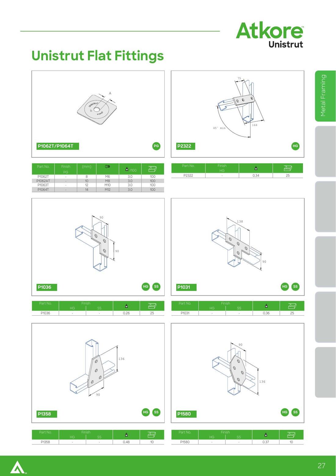
Sizes, masses, finishes and pack quantities are the Atkore UK catalogue’s (p. 27). Their thickness is not printed there and is inferred at 6 mm from the P1068 and P2484 fittings on the facing pages; US listings give ¼ in (6.35 mm), which is an inch dimension and is recorded without being used. The 48 mm hole pitch is a US figure, admitted only because it reproduces both printed UK sizes exactly — 21 + 48 + 21 = 90 and 21 + 48 + 48 + 21 = 138.
| Part | Shape | Size (mm) | Holes | kg | Pack | Governing load (kN) |
|---|---|---|---|---|---|---|
| P1036 | L — corner | 90 × 90 | 3 | 0.26 | 25 | 1.186 estimated |
| P1031 | T | 138 × 90 | 4 | 0.36 | 25 | 1.779 |
| P1358 | Gusset | 136 × 90 | 4 | 0.48 | 10 | no published load |
| P1580 | octagon | 90 × 136 | 4 | 0.37 | 10 | no published load |
P1031 — the one with a design load report
Atkore Unistrut Design Load Report, 2 August 2022. It gives three allowed loads defined against the plate and not against gravity, and they are nearly four times apart. Which one governs depends on how the fitting is turned, so the tool quotes the lowest.
| Axis | Direction | lbs | kN |
|---|---|---|---|
| Py | along the stem of the T | 1500 | 6.672 |
| Px | normal to the plate | 850 | 3.781 |
| Pz | along the crossbar | 400 | 1.779 |
Basis: 12 ga channel, a P1010 nut and a ½″ bolt, safety factor 2.5 on the ultimate strength of the connection. UK P1000T has a 2.5 mm wall against 12 ga’s 2.657 — 6% thinner than the section that was tested, and Atkore UK do not gauge their channel at all: the catalogue says it is cold rolled from 1.5 mm and 2.5 mm strip, so there is no UK column to read the American table across into.
Why P1036 is estimated rather than calculated
Worked from first principles the plate is good for about 23 kN in net-section rupture and 26 kN in bearing, and the ½″ bolt for about 12.6 kN in single shear. P1031’s published governing figure is 1.779 kN — seven times lower. So the plate is not what fails: the channel connection is, which is exactly why the published tables are indexed by channel gauge and not by the fitting’s own steel. Statics on the plate would produce a large number that is not an answer to the question.
What is left is a comparison with the one comparable fitting that is published. P1031 and P1036 share family, width, thickness, hole size and pitch, and each has a leg with one bolt; they differ in the other leg, three bolts against two. Scaling by that ratio is the conservative reading: 1.779 × ⅔ = 1.186 kN.
An estimate may only ever make an answer worse. A check may use this figure to fail a joint — that is information worth having — and may never use it to pass one, which would be a stamped sheet resting on a number the manufacturer never published.
Angle fittings
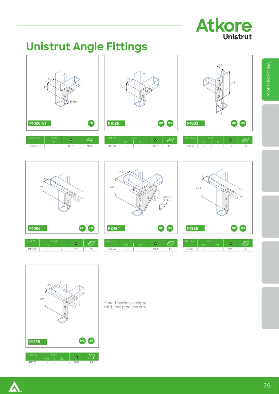
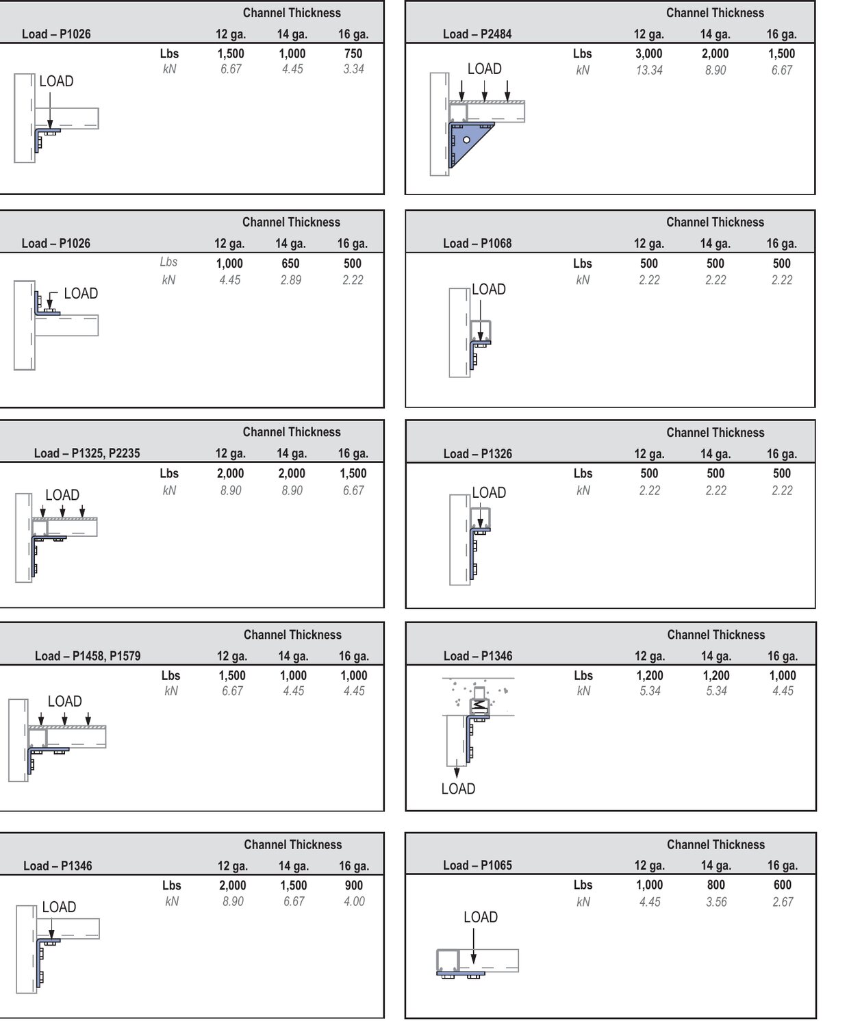
P2484 is the 90° gusset at the base of a floor-standing post. The UK catalogue prints Fmax = 4 kN; an American design-load table gives 13.34 kN at 12 ga for the same part. A 3.3× gap is a different load case or a different factor rather than a rounding difference, so the tool holds the lower figure and the discrepancy is recorded rather than resolved in favour of the larger number.
| Part | Legs × depth (mm) | t | kg | Capacity | Source |
|---|---|---|---|---|---|
| P1026 | 50 × 47 × 40 | 3 | 0.17 | rated by gauge (see below) | cat+vendor |
| P1068 | 41 × 57 × 41 | 6 | 0.17 | rated by gauge (see below) | cat+vendor |
| P1325 | 89 × 104 × 41 | 6 | 0.35 | rated by gauge (see below) | cat+vendor |
| P2484 | 102 × 102 × 47 | 6 | 0.61 | 4 kN | cat+vendor |
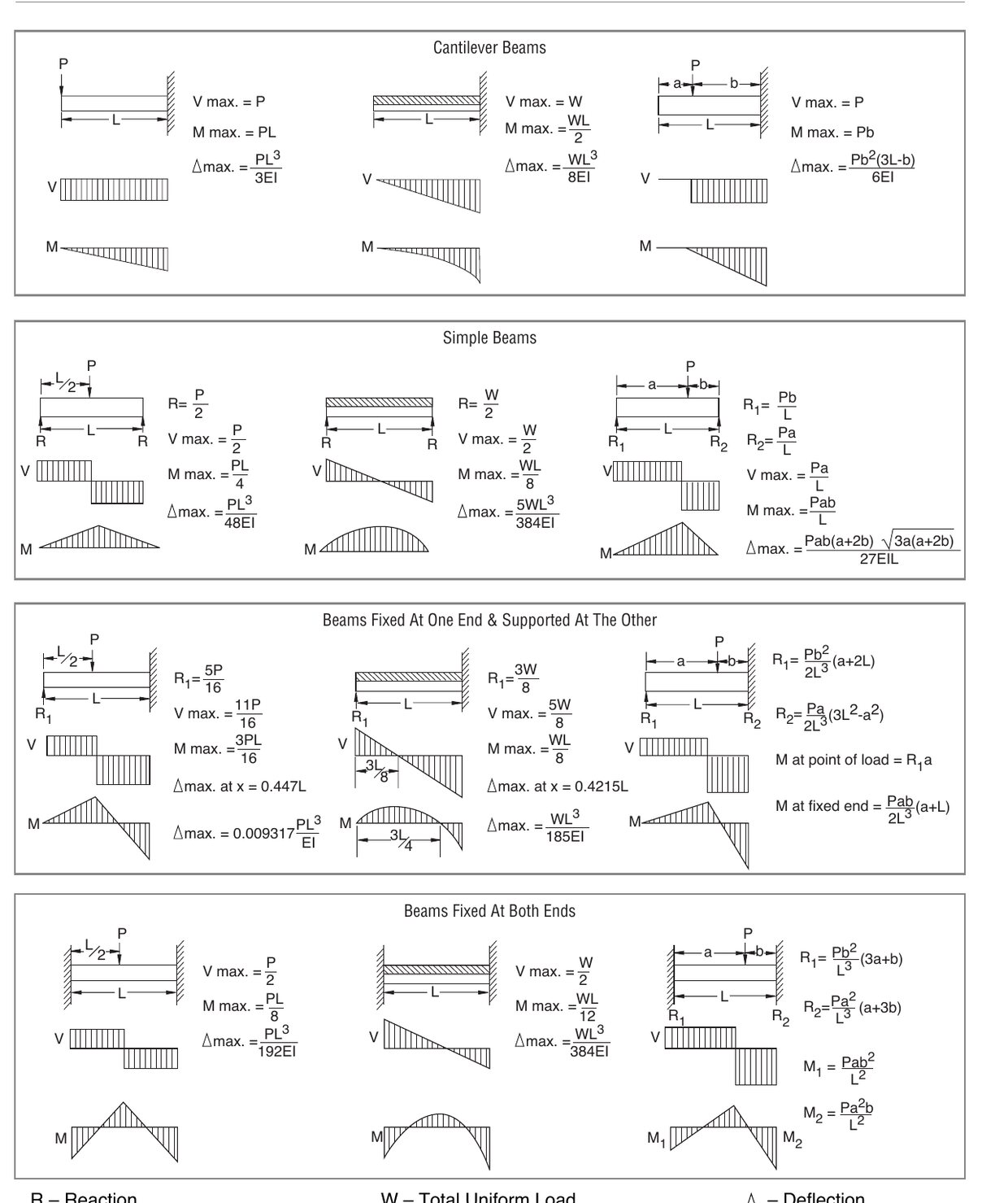
The beam cases the load diagrams are solved with
Every member the frame builder checks also carries a shear and a bending-moment diagram, drawn from the same numbers as the check. The cases are ordinary statics — they belong to mechanics, not to a manufacturer — so using them imports nothing from an American catalogue; what would be imported, and what is cited with its basis wherever it appears, is a capacity.
| Case | R | V max | M max | Where it is used |
|---|---|---|---|---|
| Simple beam, load at mid-span | W/2 | W/2 | WL/4 | a rail with one item on it |
| Simple beam, load at a from one end | Wb/L | Wa/L | Wab/L | a rail with the item off-centre |
| Simple beam, uniform load | W/2 | W/2 | WL/8 | a member carrying only its own weight |
| Cantilever, load at the end | W | W | WL | a member with one free end |
| Cantilever, uniform load | W | W | WL/2 | the same, under self weight |
W is the TOTAL load on the span. The fixed-end cases are deliberately not offered: they would be a claim about how much rotation the JOINT restrains, and a bolted channel connection through a 28 mm slot can slip up to 7 mm before anything bears. EN 1993-1-8 classifies a joint as nominally pinned when its initial rotational stiffness satisfies Sj,ini L/EI ≤ 0.5, and no such stiffness is published for these fittings. The capacities they are checked against are themselves published on the assumption that both ends of the beam are supported.
The allowable moment, and where it comes from
The catalogue prints no moment capacity for a channel — but a span table of allowable uniform loads is one. For a simply supported beam M = W × L / 8, and a section’s moment capacity cannot depend on the span it happens to be used over, so if the strength column really is a strength column that sum must come back the same on every row. It does — which is what makes the figure quotable, and it is an identity applied to published numbers rather than a derivation of our own.
| Channel | Spans | W·L/8 across them (kN·m) | Spread | Allowable moment (kN·m) |
|---|---|---|---|---|
| P1000T | 12 | 0.5022 … 0.5003 | 0.63 % | 0.5018 |
| P3300T10 | 8 | 0.1610 … 0.1610 | 0.08 % | 0.1610 |
| P1001TFR | 10 | 1.5340 … 1.5341 | 0.11 % | 1.5341 |
The tool takes the median — one rounded row cannot drag it — and refuses the figure entirely above a 3 % spread: a column that is not flat is not a pure strength column, and no moment may be read from it. A post is then checked on N/Nc + M/Mc ≤ 1, the linear interaction, which is the conservative form; a more refined one needs buckling and section-class data this tool does not hold.
Channel nuts — the UK connection table
Atkore UK catalogue p. 24. The figure on that page marks two directions and tabulates only one: F3 runs along the bolt and pulls the nut out through the mouth; F4 runs along the channel and slides the nut in its slot. A number for one is not a number for the other. The torque is part of the figure, not a footnote to it.
| Finish | Channel | Nut | Torque (Nm) | F3 (kN) |
|---|---|---|---|---|
| ZP | P1000 | PNP06 | 12 | 4.2 |
| ZP | P1000 | PNP08 | 28 | 4.7 |
| ZP | P1000 | PNP10 | 55 | 6 |
| ZP | P1000 | PNP12 | 70 | 8 |
| ZP | P1000 | PNP16 | 125 | 10.3 |
| ZP | P3300 | PNS06 | 12 | 4.2 |
| ZP | P3300 | PNS08 | 28 | 4.7 |
| ZP | P3300 | PNS10 | 55 | 6 |
| ZP | P3300 | PNS12A | 60 | 6 |
| ZP | P4000 | PNL06 | 12 | 4.2 |
| ZP | P4000 | PNL08 | 28 | 4.7 |
| ZP | P4000 | PNL10 | 40 | 6 |
| ZP | P4000 | PNL12A | 60 | 8 |
| SS | P1000 | PNP06 | 6.5 | 2.2 |
| SS | P1000 | PNP08 | 16 | 3.97 |
| SS | P1000 | PNP10 | 31.5 | 6 |
| SS | P1000 | PNP12A | 55 | 6 |
| SS | P3300 | PNP06 | 6.5 | 2.45 |
| SS | P3300 | PNP08 | 16 | 4.41 |
| SS | P3300 | PNP10 | 31.5 | 6.86 |
| SS | P3300 | PNP12A | 55 | 6.86 |
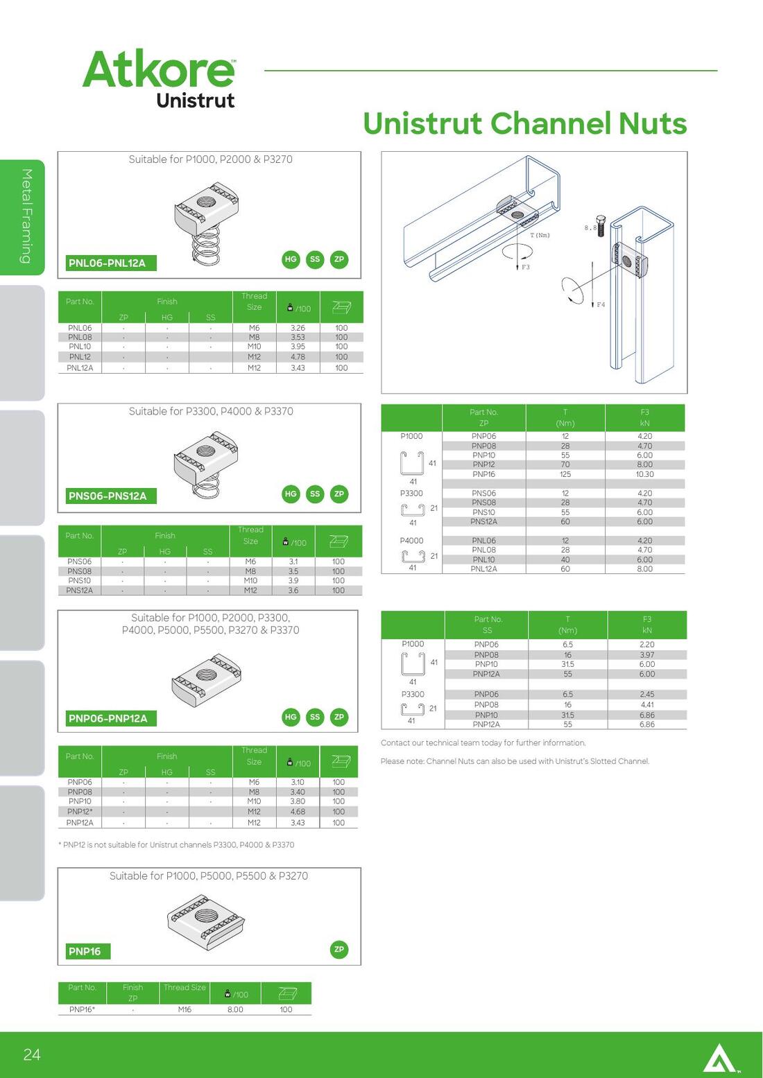
HG is not published. The nuts are sold zinc-plated, hot-dip galvanised and stainless, and only ZP and SS carry an F3 — which matters, because both of the drawings this section was written against specify HG.
What the frame builder does NOT check
- Frame stability and sway. A floor-standing frame stands up because its base gussets resist moment, and no moment capacity is published for any of these fittings. The members are checked against their own tabulated capacities; holding the frame up is the engineer’s.
- Second-order effects. No P-delta, no imperfection allowance.
- Raking members. Frames here are orthogonal; a diagonal is rejected rather than silently scheduled as if it were square.
- The fixing into the structure beyond the anchor’s own rating — edge distances, spacing, concrete condition and the slab itself remain to be verified.
Sources and what to verify
- BS 8519:2020 — Annex E (normative): the drop-rod sizing formula, Table E.1 allowable stress in fire, Table E.2 thread details. Annex I (informative): the load share between rods.
- BS 3643-2:2007 — ISO metric thread minor diameters, via Table E.2.
- Atkore Unistrut & Marco catalogue — channel load tables, section properties, the PNP12 channel nut.
- Atkore Unistrut & Marco catalogue p. 24 and p. 27 — the channel-nut F3 connection table (F4 is drawn and never tabulated) and the flat fittings. Neither page publishes a load for P1036, P1358 or P1580.
- Atkore Unistrut Design Load Report, P1031 (4-Hole, Flat Plate Fitting), 2 August 2022 — the only fitting in the frame builder with a published rating, and the source of its three allowed loads.
- Atkore Unistrut FR Range — independent fire resistance test to BS EN 1363-1:2020.
- Lindapter DECKFIREUK24 / BRE P116310 — VN wedge nut. Hilti ETA-13/1038 — HUS3 screw anchor.
- BS EN 61537 — containment load/span testing. Wind, snow, ice, seismic and thermal forces are excluded from those tests and left to the installation designer.
- IET Guide to Cables and Cable Management §8.4.4–8.4.7 — the load calculation, the drop-rod share and the containment-span check.
What carries a VERIFY mark, and why
A VERIFY value is one that must be confirmed against current manufacturer literature before a calculation is issued. Three kinds appear on this page:
- Indicative catalogue data — correct when transcribed, but editions change. Channel tables, anchor ratings, containment weights.
- The tool's own assumptions — values no document supplies: the ambient rod stress, the strut factors for an uplifted rod, the fraction of a channel nut's capacity assumed usable in fire.
- Read-across — a published figure applied to something it was not measured on. The cantilever in fire is the clearest case, and the sheet says so.
Every calculation counts how many VERIFY values it actually used and prints the number. A calculation with none is not possible; a calculation where you have checked each one is defensible.
This calculator is a design aid for cable-containment support engineering to BS 8519:2020, not a substitute for a structural engineer's assessment. The exported spreadsheet — with its working visible — is the record of calculation. Loading assumptions, fixing capacities and site conditions remain the responsibility of the design engineer.